
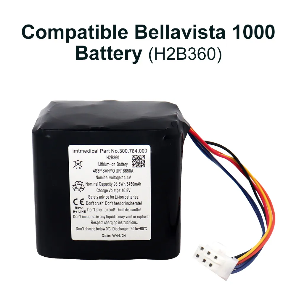
When we design a medical battery pack, the connector, wiring harness, and enclosure are not separate accessories—they are the backbone of electrical safety, EMC stability, and long-term reliability. In our work as a medical device battery manufacturer, we treat A Guide to Selecting Connectors, Wiring, and Enclosures for Medical Battery Packs as a systems-engineering process: define the clinical use case, match the electrical interface, validate the harness under real-world strain, and confirm the enclosure can protect the pack across sterilization, vibration, ingress, and cleaning cycles. For both first-time buyers and experienced OEM engineers, the most reliable path is to start with application requirements, verify compliance against standards such as ASTM, DIN, IEC, and UL, and then move through connector selection, conductor sizing, strain relief, and enclosure architecture in a staged, test-driven way. At HUIREN, we use precision-controlled assembly, dimensional checks to 0.01 mm, and 100% inspection at critical process points so customers can move from concept to qualification with fewer redesigns and shorter validation cycles.
In medical power systems, a battery pack failure rarely comes from the cell alone. More often, the root cause is interface failure: a loose latch, undersized wire, poor overmold geometry, or an enclosure that does not tolerate cleaning chemistry. That is why A Guide to Selecting Connectors, Wiring, and Enclosures for Medical Battery Packs must begin with the operating environment, not the part catalog.
We usually start by mapping four risk zones:
Electrical load
Continuous current
Peak discharge current
Inrush and hot-plug behavior
Contact resistance limits
Mechanical stress
Pull force
Bend radius
Vibration and drop exposure
Mating-cycle durability
Clinical environment
Wipe-down disinfectants
Fluid ingress
Sterilization proximity
Temperature/humidity cycling
Regulatory target
IEC 60601 alignment
UL safety expectations
ASTM and DIN test references
OEM-specific acceptance criteria
A medical device battery manufacturer that ignores these variables usually ends up with repeated redesigns. By contrast, a structured specification process reduces ambiguity and improves first-pass validation.
Before we select a connector pinout or choose a thermoplastic enclosure, we define the application precisely. This is where many projects either gain momentum or stall.
For example, we ask:
Is the device portable, wearable, bedside, or cart-mounted?
Will the pack be user-swappable or service-only?
Must the interface support charging while operating?
Is the battery exposed to routine hospital disinfection?
Will the unit face splash, sweat, blood, or fluid wipe-downs?
What is the allowable profile thickness and weight budget?
Once these answers are clear, the architecture becomes much easier to optimize. In one HUIREN program for a compact diagnostic device, the customer initially specified a generic circular connector. After we reviewed the actual cable routing and clinical use cycle, we switched to a polarized low-profile medical connector with better strain relief and shorter harness length. That change reduced assembly variance and eliminated two cable-failure modes during drop testing.
This is the practical starting point for A Guide to Selecting Connectors, Wiring, and Enclosures for Medical Battery Packs: define the mission first, then engineer the hardware around it.
Connector selection is never just about mating type. It is about the full interface behavior across thousands of cycles.
Current and voltage capability
Confirm steady-state and peak load.
Check derating at elevated temperature.
Match pin count to power and signal separation.
Contact integrity
Low contact resistance
Stable insertion/extraction force
Anti-misinsertion keying
Vibration-resistant retention
Clinical usability
One-handed docking
Audible/tactile feedback
Glove-friendly geometry
Easy cleaning around recesses and seams
Durability
Cycle life target
Latching endurance
Corrosion resistance
Compatibility with humid environments
Safety and compliance
Touch-proof design
Creepage and clearance
Polarization
Alignment with IEC, UL, and relevant DIN connector requirements
For medical battery packs, we often recommend connectors that can support both power and communication signals in a single interface when the use case allows it. However, we do not force consolidation if it increases noise coupling, thermal load, or service risk. That is where engineering judgment matters.
| Selection factor | What to verify | Why it matters |
|---|---|---|
| Current rating | Continuous and peak load | Prevents overheating |
| Mating cycles | Required lifecycle count | Ensures service durability |
| Retention force | Pull-out resistance | Reduces accidental disconnect |
| Polarization | Keyed geometry | Prevents reverse connection |
| Sealing level | IP requirement | Protects against fluid ingress |
| Contact plating | Wear and corrosion resistance | Improves long-term stability |
At HUIREN, we support connector qualification with in-process inspection, fit verification, and dimensional control to 0.01 mm where interface geometry demands it. That level of control is especially valuable in medical battery pack connector selection for compact housings and fine-pitch interfaces.
Once the connector is selected, the wiring harness must carry current safely and survive the mechanical environment. In our experience, wire selection is often underestimated until a harness fails during repeated flexing or thermal rise testing.
Conductor gauge
Match ampacity to load and temperature rise.
Avoid oversizing so heavily that routing becomes impossible.
Stranding and flexibility
Fine-strand conductors improve bend life.
High-flex wire is essential in portable or removable packs.
Insulation material
Evaluate PVC, XLPE, silicone, or other medical-suitable constructions.
Confirm resistance to cleaning agents and heat.
Harness routing
Minimize sharp edges and pinch points.
Maintain safe bend radius.
Separate power and signal paths when needed.
Termination quality
Crimp pull-force validation
Solder joint reliability where appropriate
Potting or overmolding for strain relief
Calculate current and temperature rise
Verify worst-case operating condition.
Include charge mode and discharge mode.
Choose conductor size
Select wire gauge with sufficient margin.
Validate against acceptable voltage drop.
Design routing and retention
Add clips, channels, or adhesive supports.
Prevent chafe against enclosure edges.
Validate terminations
Conduct pull testing.
Inspect crimp height and conductor strip length.
Confirm mechanical endurance
Run flex, vibration, and insertion-cycle checks.
A medical device battery manufacturer should not treat the harness as a generic cable assembly. It is a qualified subassembly, and in many cases it is the first element to reveal design weakness. For that reason, A Guide to Selecting Connectors, Wiring, and Enclosures for Medical Battery Packs must include harness validation as a formal step, not an afterthought.
The enclosure is where electrical, mechanical, and clinical requirements converge. The wrong housing can trap heat, complicate sterilization, or introduce seam leakage. The right housing protects the pack while remaining serviceable and manufacturable at scale.
Copyright:@2020-2021

Comments Please sign in or sign up to post.
0
0 of 500 characters used