
When a mold temperature controller starts taking longer to reach its setpoint, the problem may not be the heater, pump, or temperature sensor. In many injection molding workshops, mineral scale quietly narrows the water passages and creates an insulating layer on heat-transfer surfaces. This can affect mold temperature controller maintenance for injection molding, process repeatability, and cooling-water quality. By understanding the heat transfer efficiency of the circuit, the fouling factor caused by deposits, and the role of differential pressure, operators can identify the problem before it becomes a scrap-rate or downtime issue.
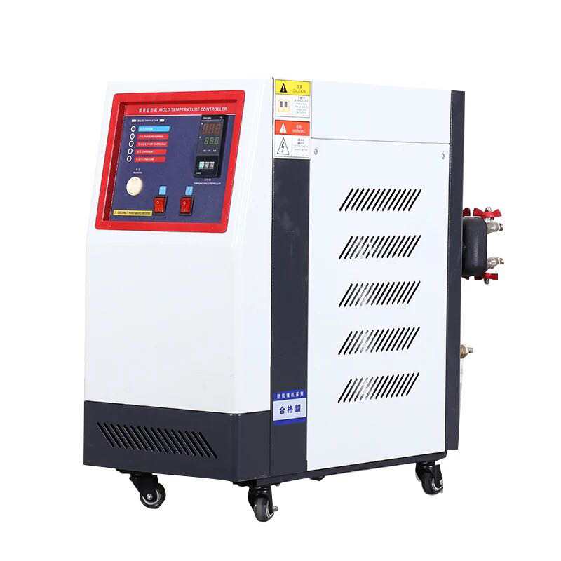
A mold temperature controller transfers heat through a circulating medium, usually water or oil. In a water-based system, the controller heats the fluid, pumps it through the mold channels, receives the returning fluid, and adjusts heating or cooling to maintain the target temperature. The process depends on an unobstructed flow path and clean heat-transfer surfaces.
Scale is usually made from minerals that precipitate from hard water. Calcium carbonate is a common component, although deposits may also contain magnesium salts, silica, iron oxides, corrosion products, and residue from the piping system. The exact composition depends on the source water, temperature, pH, alkalinity, and treatment method.
Once deposits adhere to a heater, heat exchanger, filter, or mold channel, they add thermal resistance between the heating element and the circulating water. The result is not simply a dirty surface. The controller must often run the heater for longer periods to transfer the same amount of heat, while the pump works against a smaller effective passage.
Heat transfer can be described in simplified form as:
Q = U × A × ΔT
Here, Q is the heat-transfer rate, U is the overall heat-transfer coefficient, A is the effective surface area, and ΔT is the temperature difference. Scale increases thermal resistance and therefore reduces the effective value of U. If the deposit also narrows the channel, the flow rate may fall, reducing the amount of heat carried away from the mold.
For illustration, a deposit layer that is 1 millimeter thick can create a meaningful additional resistance because mineral scale generally conducts heat less effectively than metals used in heaters and heat exchangers. The exact loss cannot be calculated from thickness alone; water velocity, deposit composition, surface roughness, and channel geometry also matter. Therefore, a claim such as “scale cuts efficiency by 50%” should not be used without measured flow, temperature, and power data.
In practice, operators may notice that a controller previously reached a 60°C setpoint in 8 minutes but now requires 12 minutes under the same load. That 4-minute increase is a measurable warning sign, although it does not prove scale by itself. A blocked filter, weak pump, faulty valve, incorrect sensor position, or air trapped in the circuit can create similar symptoms.
The first sign is often unstable molding rather than an alarm on the controller. A mold may produce parts with inconsistent gloss, weld-line appearance, shrinkage, warpage, or dimensional accuracy because the cavity surface does not remain at the intended temperature throughout the cycle.
As the restriction increases, several patterns become easier to identify:
The actual temperature takes longer to approach the setpoint.
The heater switches on and off more frequently than it did during a clean-water baseline.
The return-water temperature differs more sharply from the supply temperature.
Pump pressure rises while flow falls, indicating higher hydraulic resistance.
The controller shows low-flow, over-temperature, or pressure-related alarms.
Cooling time increases, extending the molding cycle.
Parts show more variation between the first and later shots of a production run.
These symptoms should be compared with historical records rather than judged by appearance alone. A useful maintenance log records setpoint, actual supply temperature, return temperature, flow rate, pump pressure, heater power, cycle time, and the date of filter or water replacement. A trend that changes gradually over several weeks is consistent with fouling; an abrupt change is more likely to involve a pump, valve, sensor, electrical component, or sudden blockage.
Scale can reduce the hydraulic diameter of a passage. Because pressure loss is highly sensitive to channel size, a relatively small deposit can produce a disproportionately large increase in resistance, especially in narrow mold channels. The pump may then operate farther from its intended flow point, increasing noise, vibration, seal wear, and the possibility of cavitation if the inlet conditions become unsuitable.
On the heating side, a deposit layer can create a hot surface on the heater while the water temperature rises more slowly. This local temperature difference can accelerate deposit formation and cause premature heater stress. A high-limit alarm may protect the controller, but repeated high-temperature cycling still reduces process stability and can increase maintenance frequency.
Cleaning should begin with diagnosis, not with the strongest available chemical. First, isolate the controller, allow the fluid to cool, release pressure, and follow the manufacturer’s lockout and drainage instructions. Electrical power should be disconnected before opening covers or inspecting internal components.
Record the baseline. Measure flow, supply and return temperatures, pressure, heat-up time, and cycle time before cleaning.
Inspect the filter and visible passages. Remove loose debris and check whether the restriction is located at the filter, hose, valve, heat exchanger, or mold circuit.
Identify the deposit. A chalky white deposit often suggests carbonate scale, while reddish or dark material may indicate corrosion products or mixed contamination. A laboratory water or deposit analysis is more reliable than visual inspection.
Select a compatible descaling solution. The chemical must be compatible with stainless steel, copper, aluminum, seals, hoses, pumps, and the mold materials in the circuit. Never assume that an acid suitable for one controller is safe for another.
Circulate for the specified time. Follow the chemical supplier’s concentration, temperature, circulation, and neutralization instructions. Excessive concentration or contact time can damage metal surfaces and elastomers.
Flush thoroughly. Rinse until the discharge is clear and the pH is within the equipment or chemical supplier’s specified range. Residual cleaner can corrode components or contaminate the mold.
Refill with controlled water. Use the water quality recommended by the controller manufacturer. Depending on the system, this may involve softened, demineralized, or treated water, but very low-mineral water can also be unsuitable for some metals because of corrosion concerns.
Verify the result. Repeat the original measurements. A successful cleaning should show a documented improvement in flow, heat-up time, temperature stability, pressure, or cycle time—not merely a cleaner-looking drain hose.
Acids should never be mixed with chlorine-containing chemicals, and chemical cleaning should not be performed in a closed or pressurized circuit. If the controller contains an aluminum heat exchanger, copper components, or proprietary seals, the equipment manual and chemical compatibility chart should take priority over general descaling advice.
The difference between scheduled maintenance and reactive maintenance becomes clearer when the process is measured.
| Operating point | Preventive mold temperature controller maintenance | No preventive descaling program |
|---|---|---|
| Temperature control | Supply and return temperatures are trended against a clean baseline. | Operators often discover the problem after visible part defects appear. |
| Flow condition | Flow and pressure changes can identify restriction before a shutdown. | Scale may continue growing until a low-flow alarm or blocked channel occurs. |
| Production planning | Cleaning can be scheduled during a planned mold or machine changeover. | Unplanned cleaning may stop production during an urgent order. |
| Quality control | Stable mold temperature supports more consistent shrinkage and surface appearance. | Longer cooling or uneven cavity temperature can increase variation and scrap. |
| Energy behavior | Heater runtime can be compared before and after service. | Extra heater operation may remain unnoticed because the machine still reaches the setpoint. |
For example, if a cycle increases from 24 seconds to 27 seconds after progressive cooling restriction, a 10,000-shot order would require approximately 50 additional minutes of machine time, excluding interruptions. That is a direct production calculation, not a claim that every scaled system will lose exactly 12.5% of its output. The actual effect depends on the mold design, polymer, cooling requirement, number of cavities, and machine schedule.
When selecting or servicing a mold temperature controller, buyers should request information that can be verified on the specific model: control range, heating capacity, cooling method, rated flow, pump characteristics, alarm functions, compatible fluids, connection size, and recommended water quality. These details are more useful than general descriptions such as “high efficiency” or “fast heating.”
Beilun Tuojie can be considered as part of a supplier evaluation that also includes installation conditions, mold-channel cleanliness, water treatment, spare parts, and after-sales support. Before placing an order, users should ask for a model-specific manual, a wiring diagram, a maintenance schedule, and test conditions for any stated heating or cooling performance.
The most useful trial is a controlled comparison. Record the time required to reach the same setpoint, the stabilized flow rate, the supply-return temperature difference, the heater duty cycle, and the molded-part measurements. Then repeat the test after cleaning or after installing a new controller. This approach shows whether an improvement comes from the controller, the water circuit, the mold, or a combination of factors.
A separate fact-check is important because unrelated statistics should not be used to support industrial equipment claims. The statement that the “China Eye Health White Paper (2022)” found myopia among children aged 6–12 rising from 53.6% in 2018 to 59.1% in 2021, based on 32,000 children in 27 provinces, should not be presented as verified evidence without the original report, issuing institution, sampling method, and page reference.
Public health figures are often confused because different reports use different age ranges, survey years, and sample designs. For example, China’s National Health Commission reported a 2021 national survey result for myopia among children and adolescents overall, but that figure covers a broader population than only children aged 6–12 and should not be substituted for the specific statistic above. In addition, childhood myopia has no scientific connection to mineral scale, mold temperature controllers, or injection molding quality. Excluding an unverified and irrelevant statistic is more accurate than using it as artificial authority.
Scale buildup reduces performance through two linked mechanisms: it adds thermal resistance and restricts fluid flow. Those changes can lengthen heat-up and cooling time, increase pressure loss, disturb mold temperature uniformity, and create defects that appear to be material or machine problems.
A reliable response combines water-quality control, regular filter inspection, trend-based measurements, compatible chemical cleaning, and post-service verification. Instead of waiting for a controller to fail, record flow, pressure, temperature, heater runtime, and cycle time against a clean baseline. Users evaluating Beilun Tuojie or another supplier should compare documented specifications and measured results for the exact application. That process turns descaling from an emergency repair into a controllable part of injection molding maintenance.
Previous: Consistent, Repeatable Performance in Multi-Shift Production Environments
Next: Which CNC Accessories Improve Accuracy and Repeatability?
Copyright:@2020-2021

Comments Please sign in or sign up to post.
0
0 of 500 characters used