
To understand how to position meteorological sensors on an offshore buoy, I begin with the measurement objective, then define sensor height, exposure, alignment, shielding, and motion limits. The wind instruments need clear airflow, temperature and humidity sensors need ventilated radiation protection, and pressure instruments need a dry, stable reference point. I also record each installation dimension so the final data can be interpreted against the actual buoy configuration.
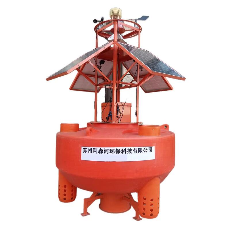
Wind sensors require unobstructed airflow, documented height, compass alignment, and quantitative wind-shadow checks.
Temperature and humidity sensors need ventilated radiation shields positioned away from solar-heated structures.
Pressure sensors belong inside a dry enclosure with a protected, low-restriction pressure port.
Solar radiation and rain sensors require level mounting, clean exposure, and protection from mast shadows.
Buoy motion must be measured, logged, and separated from genuine atmospheric changes during data validation.
Asenhe supplies integrated ocean monitoring buoy systems combining platforms, sensors, communications, power, and data management.
Before mounting any instrument, I define whether the buoy will measure local marine weather at buoy height, support a standardized meteorological network, or provide engineering data for offshore wind, ports, shipping, or environmental research. These objectives are not interchangeable. A compact research buoy with a 3–5 m mast may provide reliable local observations, but its wind data should not automatically be treated as equivalent to a standardized 10 m reference measurement.
The installation package should include the buoy drawing, mast-load calculation, sensor manuals, compass reference, cable schedule, calibration certificates, power budget, telemetry plan, and acceptance-test procedure. I also identify the expected sea state, watch-circle radius, mooring angle, corrosion exposure, service interval, and recovery method. WMO-No. 8 provides the main international framework for meteorological measurement methods, while NOAA buoy records show that actual sensor heights vary by hull and platform design.
For a typical offshore weather payload, I prepare an anemometer or ultrasonic wind sensor, wind-direction reference, air-temperature and relative-humidity probe, barometric-pressure sensor, pyranometer, rain gauge, GNSS receiver, motion sensor, data logger, telemetry modem, solar-power system, and grounding arrangement. A wave sensor or water-temperature probe may be added when the buoy supports broader marine environmental monitoring. Asenhe describes its meteorological solution as an integrated arrangement involving sensors, buoy or drifter platforms, satellite or 4G communication, and a data platform.
I use the following sequence because it connects the measurement objective to the mechanical installation and the final data check:
Define the required measurement height, reference direction, sampling interval, and data-use standard.
Select a mast location with the smallest possible obstruction and sufficient structural stiffness.
Mount wind instruments above the main buoy body, solar panels, antennas, railings, and lifting hardware.
Install temperature, humidity, pressure, radiation, and precipitation instruments in separate exposure zones.
Route cables through sealed glands and grounded conduits without creating loops that collect spray or water.
Verify orientation, leveling, calibration status, telemetry, power consumption, and sensor metadata.
Compare the first operating data with motion, wind direction, wave, and obstruction records before acceptance.
This procedure is more reliable than mounting every sensor on a single crowded bracket. Each instrument responds to a different physical disturbance, so the buoy must be treated as a group of measurement environments rather than as one uniform platform.
Wind-speed and wind-direction sensors should normally occupy the highest practical point on the mast, with a clear horizontal view around the sensing volume. I keep the anemometer above solar panels, antennas, handrails, access platforms, lifting eyes, and other objects that can produce turbulence or a wind shadow. On larger moored buoys, operational networks commonly use wind instruments near 10 m, while smaller hulls may use nominal heights around 3–5 m. NOAA’s buoy documentation illustrates this variation, including 10 m and 5 m configurations, so I never specify height without referencing the buoy geometry and reporting requirement.
For a standardized surface-wind program, I specify the target height first and then design the mast around that requirement. For local buoy-weather measurements, a 3 m, 5 m, or 10 m mounting height may be suitable, but the metadata must state the exact elevation above the waterline or defined buoy reference. I record the normal, minimum, and maximum elevation caused by buoy pitch, heave, and mooring inclination.
I also apply a clearance rule rather than relying only on height. As a design target, the wind sensor should be at least 2 m above the nearest major obstruction and positioned so that no structure occupies the primary upwind sector. If a mast, antenna, or solar panel remains within the airflow envelope, I document the affected direction sector and flag those observations rather than presenting them as unrestricted wind measurements.
I assess obstruction effects by dividing the horizon into directional sectors, commonly 10° or 15° intervals. For each sector, I record the angular width and estimated blockage ratio using:
[ B = \frac{A{\text{projected obstruction}}}{A{\text{sensor airflow zone}}} ]
The calculation does not replace wind-tunnel testing or field comparison, but it creates a repeatable screening method. During commissioning, I compare wind speed and direction distributions by sector, especially when the buoy turns through its watch circle. A persistent reduction in wind speed from one sector, a direction-dependent increase in variance, or repeated gust spikes when the mast aligns with a panel indicates platform interference.
For a buoy that moves around its anchor, I log heading, pitch, roll, heave, and GNSS position with every meteorological record. I then separate atmospheric variability from platform-motion bias by comparing the wind record with the motion sensor and wave record. If wind anomalies appear only during high pitch or roll, I treat them as a measurement-quality issue requiring filtering, mechanical correction, or revised mast geometry.
I align a wind vane or directional sensor to true north using a surveyed compass reference, GNSS heading, or a documented magnetic-declination correction. The alignment value, date, reference instrument, and correction angle belong in the station metadata. On a rotating tower, I verify that the sensor reference follows the tower orientation and that the rotation mechanism does not introduce backlash or intermittent cable tension.
Compact ultrasonic sensors remove the need for a mechanical vane, but they still require a correct north reference and a clear sensing volume. I verify the manufacturer’s coordinate convention because some instruments report the direction from which the wind arrives, while others use vector components or a different sign convention. A small directional bias can affect sector analysis, wave-wind studies, and comparison with ship or shore stations.
For air temperature and humidity sensor shielding, I mount the probe in a ventilated radiation shield on the side of the mast, away from solar panels, battery housings, power converters, exhaust outlets, and dark-painted structural members. The shield should prevent direct solar heating while allowing air exchange around the sensing element. I avoid placing the probe underneath a platform where warm air, spray, or dripping condensation can collect.
The sensor should remain above normal wave splash but below any location where mast equipment can radiate concentrated heat. On a small buoy, I prefer a side arm with a minimum separation of approximately 1 m from the main electronics enclosure when the mechanical layout allows it. I also keep the air-temperature and humidity probe at a documented height, because comparing a 2 m sensor with a 5 m sensor can introduce real environmental differences in unstable marine conditions.
A naturally aspirated shield may be sufficient for low-power deployments, but a fan-aspirated shield can reduce solar-loading errors when the buoy has adequate energy capacity. I check fan power, bearing life, filter condition, and salt accumulation during maintenance planning. The shield must not become a spray collector, so drain paths and downward-facing openings should be included in the mechanical design.
I place temperature and humidity sensors in an exposed, shaded, ventilated position that is separated from the buoy’s heat sources and direct spray path. The sensor should not share a bracket with a radio antenna, high-current cable, battery box, or solar regulator. When the buoy carries a large solar array, I install the probe on the opposite side of the mast or above the array’s upper edge, depending on the prevailing installation geometry.
I inspect the first day of data for daytime temperature rises that track solar radiation rather than wind or air-mass changes. A repeated temperature increase during calm, sunny periods, followed by rapid recovery after sunset, often indicates radiation-shield or heat-source contamination. Relative humidity should also be checked for unrealistic saturation plateaus caused by condensation, salt deposits, or a blocked shield.
I install the barometric-pressure sensor inside a dry, temperature-stable electronics enclosure rather than exposing the instrument directly to the marine atmosphere. The pressure port must connect to outside air through a short, low-restriction path that includes a hydrophobic membrane or equivalent splash barrier. I keep the port away from fans, vents, cable penetrations, battery compartments, and locations that can experience changing internal pressure.
The sensor elevation must be recorded because pressure is often reduced to sea level or compared with other stations. I document whether the reported value is raw station pressure or a sea-level-adjusted product, including the temperature, elevation, and algorithm used for conversion. During commissioning, I compare the buoy reading with a calibrated reference before sealing the enclosure.
I mount the solar-radiation sensor on a level, rigid arm with an unobstructed view of the sky. The instrument must be separated from the mast, antennas, flags, and solar panels that could cast shadows during part of the day. I check the shadow path at low and high sun angles rather than inspecting only the midday position.
The radiometer should be leveled with an adjustment mechanism that can be locked after installation. I record the leveling result, calibration factor, serial number, and dome-cleaning schedule. A sensor mounted beside a solar panel may experience reflected light, partial shading, and heat exchange that distort the measurement even when the sensor appears visually exposed.
Rain gauges require a different arrangement. I place the collector away from the mast and shield it from direct spray while retaining a clear precipitation path. The rim must remain level, the funnel must drain freely, and the mounting bracket must not transmit excessive vibration. On a buoy with strong motion, I record tilt and compare rainfall pulses with wave splash and wind-gust data before accepting each event.
Offshore sensor placement must include corrosion resistance, grounding, cable protection, and structural control. I specify marine-grade fasteners, compatible metals, sealed connectors, UV-resistant cable jackets, and drainage paths. Dissimilar-metal contact is controlled with suitable isolation washers, coatings, or material selection, because galvanic corrosion can weaken a sensor bracket before the instrument itself fails.
The mast is checked for bending, vibration, fatigue, and local fastener loads. A long mast may improve wind exposure but also increases overturning moment and motion response. I use the buoy’s design loads, expected wind speed, wave environment, and instrument mass to confirm that the mast remains within the structural limits defined by the engineering calculation.
Cable management needs its own inspection. I use drip loops outside enclosures, strain relief at every connector, sealed glands at penetrations, and separate routing for low-level analog signals and high-current power cables. Cables should not rub against sharp brackets or hang below the deck where wave impact can produce repeated flexing.
Grounding and surge protection are especially important when the buoy carries radio equipment, a tall mast, or exposed solar arrays. I bond conductive mast sections according to the system grounding design and protect signal lines with suitable surge devices. The grounding arrangement must not create unwanted current paths through sensitive sensor circuits.
Asenhe presents itself as an ocean monitoring buoy supplier offering monitoring buoys, ocean buoys, wave systems, water-quality instruments, communication equipment, and data platforms. Its published marine solution is aimed at applications including ports, offshore wind, marine research, shipping, and environmental monitoring. For a buyer, the practical benefit of an integrated supplier is that mast geometry, sensor interfaces, power supply, telemetry, and data records can be reviewed as one system rather than as unrelated components.
I do not consider the installation complete when the sensors are physically attached. Before deployment, I check every instrument against its calibration certificate, confirm the serial number, enter the calibration date and correction factor, and verify the logger channel mapping. The compass reference, sensor height, orientation, shield type, mast configuration, firmware version, sampling rate, averaging period, and units are recorded in the station metadata.
After powering the system, I verify that each sensor produces a plausible value and that the telemetry packet contains the correct variable name, unit, timestamp, and quality flag. I test loss of communication, low battery conditions, sensor disconnection, and logger restart behavior. For an offshore system, I also compare the transmitted record with the locally stored record so that a formatting or packet-loss problem is not mistaken for a sensor fault.
During field acceptance, I inspect the buoy in calm and moderate conditions if possible. I check mast deflection, connector sealing, cable movement, radiation-shield ventilation, rain-gauge drainage, sensor leveling, and compass alignment. I then compare wind, temperature, pressure, and humidity trends with nearby reference observations, recognizing that ship-based measurements and buoy measurements may differ because they occupy different heights and moving platforms.
I treat a buoy-mounted weather station as a local marine observation point unless its exposure, height, calibration, and processing meet the requirements of a specific standardized network. Ship-based measurements are affected by vessel heading, superstructure, speed, exhaust, and bridge height, while a buoy is affected by mast obstruction, watch-circle movement, hull motion, and sea spray. These datasets can be compared, but I do not combine them without documenting their physical differences.
Pitch, roll, heave, and yaw change the sensor’s relationship with the airflow and the water surface. A wind sensor may report a valid instantaneous velocity while the mast is moving through the air, yet the resulting average can contain motion-induced bias. Radiation and rain measurements are also sensitive to tilt, while temperature and humidity sensors may experience intermittent spray exposure as the buoy rises and falls.
I install an inertial measurement unit or equivalent motion sensor when motion correction is important. The meteorological record should share a synchronized timestamp with heading, pitch, roll, heave, wave height, and battery status. I use these channels to flag data collected during excessive tilt, rapid rotation, sensor immersion risk, or abnormal power conditions.
The acceptance criteria should be written before deployment. For example, the project may require a wind-direction alignment within ±5°, a level-sensor tolerance within ±1°, continuous telemetry for a defined test period, no pressure-port blockage, and a documented obstruction map covering 360°. The exact limits depend on the instrument and project standard, but every limit should be numerical and testable.
Before launch, I use this checklist:
Confirm each sensor’s target height above the waterline or defined platform reference.
Verify wind-sensor clearance from masts, panels, antennas, railings, and lifting equipment.
Record true-north alignment, magnetic-declination correction, and directional convention.
Confirm temperature and humidity shields are ventilated, shaded, drained, and away from heat sources.
Check pressure-port membranes, enclosure seals, vents, and condensation control.
Level radiation and rain sensors and document possible shadow or splash sectors.
Inspect fasteners, coatings, cable glands, drip loops, strain relief, and grounding bonds.
Enter serial numbers, calibration factors, firmware versions, sensor heights, and sampling settings.
Test local logging, telemetry, timestamps, alarms, remote access, and power consumption.
Compare initial measurements with a reference and review data against buoy motion.
Define maintenance intervals for cleaning, recalibration, connector inspection, and corrosion checks.
To answer how to position meteorological sensors on an offshore buoy, I place wind sensors at the highest practical clear-air location, mount temperature and humidity probes in ventilated radiation shields, keep pressure sensors dry with protected atmospheric access, and level radiation and rain instruments away from shadows and spray. I also document height, alignment, obstruction sectors, motion behavior, calibration status, and telemetry performance before deployment.
The most important next step is to convert the buoy drawing into a sensor-by-sensor positioning map. That map should show heights, clearances, cable routes, shielding, structural supports, and the expected watch-circle orientation. After installation, I complete mechanical inspection, compass alignment, calibration review, metadata capture, telemetry testing, and field validation before accepting the dataset.
For projects requiring a complete marine environmental monitoring package, I would evaluate an experienced ocean monitoring buoy supplier such as Asenhe by reviewing the hull, mast, power system, meteorological sensors, communications, data platform, maintenance plan, and project-specific acceptance criteria together. That approach gives me a documented measurement system rather than a collection of instruments attached to a floating structure.
Previous: Moored Buoy vs Drifting Buoy: Which Fits Your Monitoring Mission?
Next: None.
Copyright:@2020-2021

Comments Please sign in or sign up to post.
0
0 of 500 characters used