
Choosing the right thermal oil boiler starts with two engineering values: required heat load and thermal oil circulation rate. In this Genjux guide, we show you how to calculate both values, select the correct heater and pump, check pressure-drop risks, and avoid common oversizing or under-circulation problems. By following the steps below, you can move from process data to a practical thermal fluid heating system specification with less rework and better operating efficiency.
A thermal oil boiler transfers heat through a circulating heat-transfer fluid rather than directly producing steam. The system must deliver sufficient energy to the process while maintaining an acceptable film temperature, flow velocity, pressure drop, and pump operating point.
If the heat load is underestimated, the system may experience:
Slow start-up and unstable production temperature
Inability to reach the target process temperature
Continuous burner operation at maximum capacity
Thermal oil degradation caused by excessive local film temperature
Reduced production output
If the circulation rate is too low, the thermal oil may remain in the heater coil too long. This increases the risk of hot spots, coking, oxidation, and uneven heat transfer. Conversely, an unnecessarily high flow rate increases pump power consumption, pipe friction, vibration, and capital cost.
For this reason, How Heat Load and Circulation Rate Affect Thermal Oil Boiler Selection is not only a sizing question. It is a complete system-design decision involving the heater, expansion tank, circulating pump, piping, control valves, burner, insulation, and safety devices.
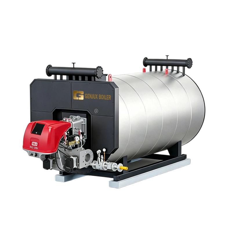
We first identify every source of heat demand. The rated capacity of a Genjux thermal oil boiler should be based on the maximum realistic operating condition, not only the average production load.
The basic heat-load equation is:
[ Q = m \times C_p \times \Delta T ]
Where:
(Q) = useful process heat load, in kW
(m) = material flow rate, in kg/s
(C_p) = specific heat capacity, in kJ/kg·K
(\Delta T) = required temperature increase, in °C or K
Add the following loads before selecting the boiler:
Product heating load
Energy required to raise the temperature of the product or raw material.
Moisture evaporation load
Include latent heat when water or solvent is evaporated.
Equipment heating load
Account for reactors, tanks, rollers, molds, heat exchangers, jackets, and other metal components.
Start-up load
Cold equipment generally needs more energy than steady-state operation.
Distribution losses
Include heat loss through piping, valves, flanges, expansion tanks, and uninsulated surfaces.
Safety margin
A typical preliminary design margin may be 10–20%, subject to process stability and local engineering practice.
Assume a process heats 5,000 kg/h of material from 20°C to 180°C. The average specific heat capacity is 2.2 kJ/kg·K.
[ m = \frac{5,000}{3,600} = 1.389 \text{ kg/s} ]
[ Q = 1.389 \times 2.2 \times (180-20) ]
[ Q \approx 489 \text{ kW} ]
If we add 15% for piping losses, start-up demand, and design margin:
[ Q_{design} = 489 \times 1.15 \approx 562 \text{ kW} ]
In this example, a Genjux thermal oil boiler with approximately 560 kW of usable process capacity may be considered for the initial design. The final selection must also confirm the required operating temperature, fuel type, thermal oil properties, altitude, and local regulations.
After calculating the heat load, we determine the thermal oil flow rate. The required mass flow is calculated as follows:
[ \dot{m}{oil} = \frac{Q}{C{p,oil} \times \Delta T_{oil}} ]
Where:
(\dot{m}_{oil}) = thermal oil mass flow rate, in kg/s
(Q) = transferred heat load, in kW
(C_{p,oil}) = specific heat capacity of the thermal oil, in kJ/kg·K
(\Delta T_{oil}) = temperature difference between thermal oil supply and return, in °C
For the previous example, assume:
Design heat load: 562 kW
Thermal oil specific heat: 2.5 kJ/kg·K
Supply temperature: 300°C
Return temperature: 270°C
Oil temperature difference: 30°C
[ \dot{m}_{oil} = \frac{562}{2.5 \times 30} ]
[ \dot{m}_{oil} \approx 7.49 \text{ kg/s} ]
This equals:
[ 7.49 \times 3,600 \approx 26,964 \text{ kg/h} ]
If the thermal oil density at operating temperature is 750 kg/m³:
[ \dot{V} = \frac{7.49}{750} \approx 0.00999 \text{ m}^3/s ]
That is approximately:
[ 36.0 \text{ m}^3/h ]
Therefore, the circulation pump must be selected for approximately 36 m³/h at the calculated system pressure head, rather than simply selecting a pump based on the boiler’s nominal capacity.
A thermal oil boiler should not be selected only by its maximum outlet temperature. We match the boiler to the actual process duty and circulation requirements.
| Design factor | What to confirm | Why it matters |
|---|---|---|
| Heat load | kW or kcal/h at peak production | Prevents under-capacity |
| Operating temperature | Supply and return temperature | Determines oil grade and heater design |
| Circulation rate | kg/h or m³/h | Controls coil heat transfer and film temperature |
| Temperature difference | Usually based on process requirements | Directly affects required flow |
| Fuel type | Natural gas, diesel, LPG, biomass, or electric | Influences burner and operating cost |
| Pressure drop | Heater coil, piping, valves, heat users | Determines pump head |
| Expansion volume | Oil expansion from cold to hot condition | Protects the system from overpressure |
| Control method | Modulating burner, bypass, or variable-speed pump | Improves temperature stability |
| Applicable code | Local pressure, combustion, electrical, and fire codes | Supports safe commissioning |
A boiler with a high thermal output but inadequate oil flow can still perform poorly. Similarly, a large pump cannot compensate for an undersized heater coil or an incorrectly calculated process load.
The thermal oil circulation rate must support adequate velocity through the heater coil and process equipment. Correct velocity improves convective heat transfer and reduces the possibility of localized overheating.
However, excessive velocity can create:
High friction loss
Increased pump power
Hydraulic noise
Erosion at elbows and control valves
Unstable flow through parallel circuits
The correct velocity depends on the thermal oil viscosity, pipe diameter, coil geometry, operating temperature, and manufacturer design. We recommend checking the Reynolds number and pressure drop for each major section of the circuit.
Thermal oil properties change significantly with temperature. A fluid that is highly viscous during cold start-up may become much thinner at 300°C. For this reason, pump selection should consider:
Cold-start viscosity
Operating viscosity
Density at supply and return temperatures
Flash point and fire point
Maximum film temperature
Recommended bulk temperature
Thermal stability and service life
Laboratory data such as kinematic viscosity can be reviewed according to ASTM D445, while density and other fluid properties should be confirmed using the thermal oil manufacturer’s technical data sheet.
The pump must deliver the required flow at the total dynamic head of the system. We calculate pressure loss from:
Thermal oil boiler coil
Supply and return headers
Heat exchangers and jackets
Control valves and balancing valves
Filters and strainers
Elbows, tees, reducers, and flexible connections
Elevation and accessory resistance
The pump operating point should be checked against the manufacturer’s pump curve. A pump that provides 36 m³/h at zero pressure is not suitable unless it can provide that flow at the actual calculated head.
We also check the pump’s NPSH requirements. Thermal oil systems operate at high temperature, and inadequate suction conditions may cause cavitation, seal damage, or unstable flow.
For practical selection, the specification should include:
Design flow rate in m³/h
Required differential pressure or head
Operating temperature range
Thermal oil viscosity range
Motor power and voltage
Seal and bearing configuration
Mechanical seal material
Cold-start condition
Variable-frequency drive requirements
A Genjux thermal oil boiler package should be evaluated together with its circulation pump, not as an isolated heater. The pump, heater coil, piping, and control system must operate as one hydraulic circuit.
Once the heat load and circulation rate are established, we verify the protective devices and control logic.
Important components include:
High-temperature limit controller
Low-flow or flow-failure protection
Burner flame-failure protection
Expansion tank and nitrogen blanket, where applicable
Pressure relief valve
Low-level alarm
Automatic bypass or minimum-flow arrangement
Emergency shutdown circuit
Oil filtration and drain provisions
Temperature sensors at boiler outlet and return
Differential-pressure monitoring
The heater should not continue firing if the circulation pump stops or the flow rate falls below the minimum required value. This interlock protects the thermal oil from overheating inside the coil.
For combustion and pressure equipment, the final design should be reviewed against applicable local requirements and recognized standards. Depending on the project location and equipment configuration, engineers may reference ASME Section VIII, EN 12952, EN 13445, DIN 4754, NFPA 87, and relevant electrical and burner standards. These references do not replace local code approval or the equipment manufacturer’s instructions.
The relationship can be summarized in four practical rules:
When production throughput, material temperature, evaporation duty, or start-up requirements increase, the boiler must provide more usable kW. A design margin should be added, but excessive oversizing may cause short cycling and poor combustion efficiency.
If the allowable oil temperature difference remains unchanged, greater heat transfer requires a higher circulation rate. This affects pump size, pipe diameter, heater-coil design, and electrical consumption.
Increasing the supply-return temperature difference reduces the required oil mass flow mathematically. However, the process may not permit a higher temperature difference, and excessive temperature gradients can cause uneven heating or product-quality problems.
The system must operate within the recommended velocity and pressure-drop range. Oversized pumps may waste energy and create hydraulic problems without improving heat transfer.
Symptoms:
Process temperature falls during peak production
Burner operates continuously
Start-up takes much longer than expected
Solution:
Recalculate product duty, moisture evaporation, equipment mass, heat loss, and peak throughput. Confirm whether the original heat-load data used average rather than maximum production conditions.
Possible causes:
Insufficient circulation
Blocked strainer or filter
Closed valve or incorrect valve position
Pump cavitation
Incorrect flow interlock
Thermal oil viscosity higher than expected
Solution:
Measure supply and return temperatures, verify pump differential pressure, inspect strainers, and confirm actual flow with an ultrasonic flow meter or calibrated flow instrument.
Possible causes:
Pipe diameter is too small
Excessive valve resistance
Pump is oversized
Thermal oil is too viscous during operation
Unnecessary bypass flow
Solution:
Complete a pressure-drop calculation, compare the actual operating point with the pump curve, and consider a variable-frequency drive where process control permits.
Possible causes:
Poor circuit balancing
Parallel branches with different resistance
Incorrect jacket or coil arrangement
Inadequate mixing at the process equipment
Low local flow velocity
Solution:
Balance each branch, install suitable flow-control valves, verify temperature sensor location, and review the heat-user design rather than increasing boiler capacity alone.
To improve selection accuracy, we recommend preparing the following resources before requesting a Genjux quotation:
Process heat-load worksheet
Material flow-rate and temperature schedule
Thermal oil technical data sheet
Piping and instrumentation diagram
Equipment layout with pipe lengths
Pump pressure-drop calculation
Heat-loss estimate
Electrical power and fuel availability data
Local pressure-vessel and combustion-code requirements
Site altitude and ambient-temperature information
Useful engineering tools include:
Spreadsheet calculations for heat load and oil flow
Piping isometric drawings for equivalent-length measurement
Pump-curve software
Thermal oil property tables
Infrared thermography for detecting insulation defects and hot spots
Ultrasonic flow measurement for commissioning verification
Differential-pressure gauges across filters and heater coils
During factory inspection and commissioning, request documented test results. Depending on the equipment scope, this may include dimensional inspection, weld inspection, hydrostatic testing where applicable, burner testing, electrical testing, control-panel verification, and performance testing. Quality documentation should identify applicable standards and acceptance criteria rather than relying only on general statements such as “fully tested.”
Before finalizing your thermal oil boiler specification, we recommend confirming these points:
Calculate the maximum process heat load in kW.
Add realistic heat losses and start-up demand.
Select the thermal oil operating and return temperatures.
Obtain the oil’s density, specific heat, and viscosity at operating conditions.
Calculate the required mass and volumetric circulation rate.
Calculate pressure loss through the complete circuit.
Match the pump to the required flow and total dynamic head.
Confirm minimum flow through the boiler coil.
Check expansion volume and safety-device sizing.
Verify burner, electrical, pressure, and fire-code requirements.
Confirm control interlocks for low flow and high temperature.
Review the complete package with the supplier before manufacturing.
The correct thermal oil boiler is selected by balancing heat load, oil temperature difference, circulation rate, pressure drop, and safety controls. By calculating the process duty first and then sizing the thermal oil flow and circulation pump, we can avoid the two most expensive mistakes: an underpowered heater and an over-pumped system.
Genjux can use your process throughput, temperature profile, thermal oil data, piping layout, and fuel conditions to develop a more reliable thermal fluid heating solution. Start with the checklist today, verify the numbers with recognized engineering methods such as ASTM D445 fluid-property testing where applicable, and request a complete boiler-and-pump review before placing the order.
Previous: How to Choose a Brushless Hand Drill?
Next: What Specifications Should You Send to a CFB Boiler Supplier?
Copyright:@2020-2021

Comments Please sign in or sign up to post.
0
0 of 500 characters used